Building an Audiovisual Synth #5: Physical Interface with ESP32 and I2C
Adding buttons, potentiometers, and encoders to the Raspberry Pi using an ESP32 and I2C connection.

To handle all input reading, I have chosen the ESP32 as an intermediary instead of connecting elements directly to the Raspberry Pi. This makes the layout more flexible, reduces the CPU load on the Pi, and enables more physical connections.
Adding Peripherals to the ESP32
The first part was to add components to the ESP32 by connecting them to one of its many pins. It took me a while to understand what all those pins do and which ones to use for specific components. In essence, there are digital and analog pins:
Digital pins can only read on/off states and can have input-pullup resistors, which are needed for buttons or encoders.
Analog pins (ADC) can convert a continuous analog signal to a 12-bit (0-4095) quantized digital signal, which is needed for potentiometers.
Next to those, there are VCC and GND pins to power components, as well as pins for I2C connections.
Understanding Component Nuances
While connecting different components to the ESP32, I discovered some details that I needed to consider.
Buttons
Buttons connect to GND and require a digital pin with an input-pullup resistor. They come in all sorts of types and sizes. The amount of pressure you need to trigger them also needs to be considered.
First, I wanted to use Cherry keyboard switches but then went with basic low-profile ones that have a feature where you can add a cap.
Potentiometers
Potentiometers are variable resistors used to create a voltage divider that changes the voltage at the center pin based on rotation. They connect to GND and VCC, and the center pin goes to an ADC pin.
Analog pins are very sensitive to noise, which you can reduce with a capacitor (which is standard, but did not work for me for space reasons) or in software with hysteresis, a rolling average, and by reducing the resolution.
In terms of options, there are many things to consider:
Resistance: I was using a 10K Ohm, which seems to be the standard for the ESP32.
General Layout and Size: The classic ones are tilted 90 degrees and are quite large. I wanted small ones that point up.
Pin Position Relative to Potentiometer Rotation: This determines the way you have to place it.
Center Detent: Does it snap when the position is in the center?
Shape and Height of the Shaft: Can you add a cap to it?
Encoders
One side has two pins for the switch, which connect to GND and a digital pin with an input-pullup. The other side has three pins for the encoder. The center pin goes to GND, and the other two connect to digital pins with input-pullups.
The encoder works in quite an interesting way by sending two pulses. By their relation to each other, the direction of rotation can be determined. It needs a library to handle that well, and the pulses per rotation also need to be selected.
The most important detail for me was the detents (how often the encoder snaps per rotation, also available without).
Sending Data Over I2C
After reading all the data with the ESP32, I needed a way to send it to the Pi. Since the Pi already uses I2C to connect to the OLED screen, it made sense to connect the ESP32 to that as well.
Initially, I had some problems with the Pi not detecting the ESP32 as an I2C device. This seemed to be solved by explicitly setting the SDA and SCL pins to use their input-pullup resistors.
In the main loop, the program reads the current state of the components and stores it in a state struct. This struct packs the data as a sequence of bytes, which gets sent to the Pi on request. The important part is to have a struct on the Pi side that has the exact same layout to unpack and use the data.
I have made a new, separate I2C thread that requests the data at certain intervals. When updates are detected, it sends State Messages to the coordinator over a crossbeam channel. This integrates quite well with the rest of the architecture I have so far.
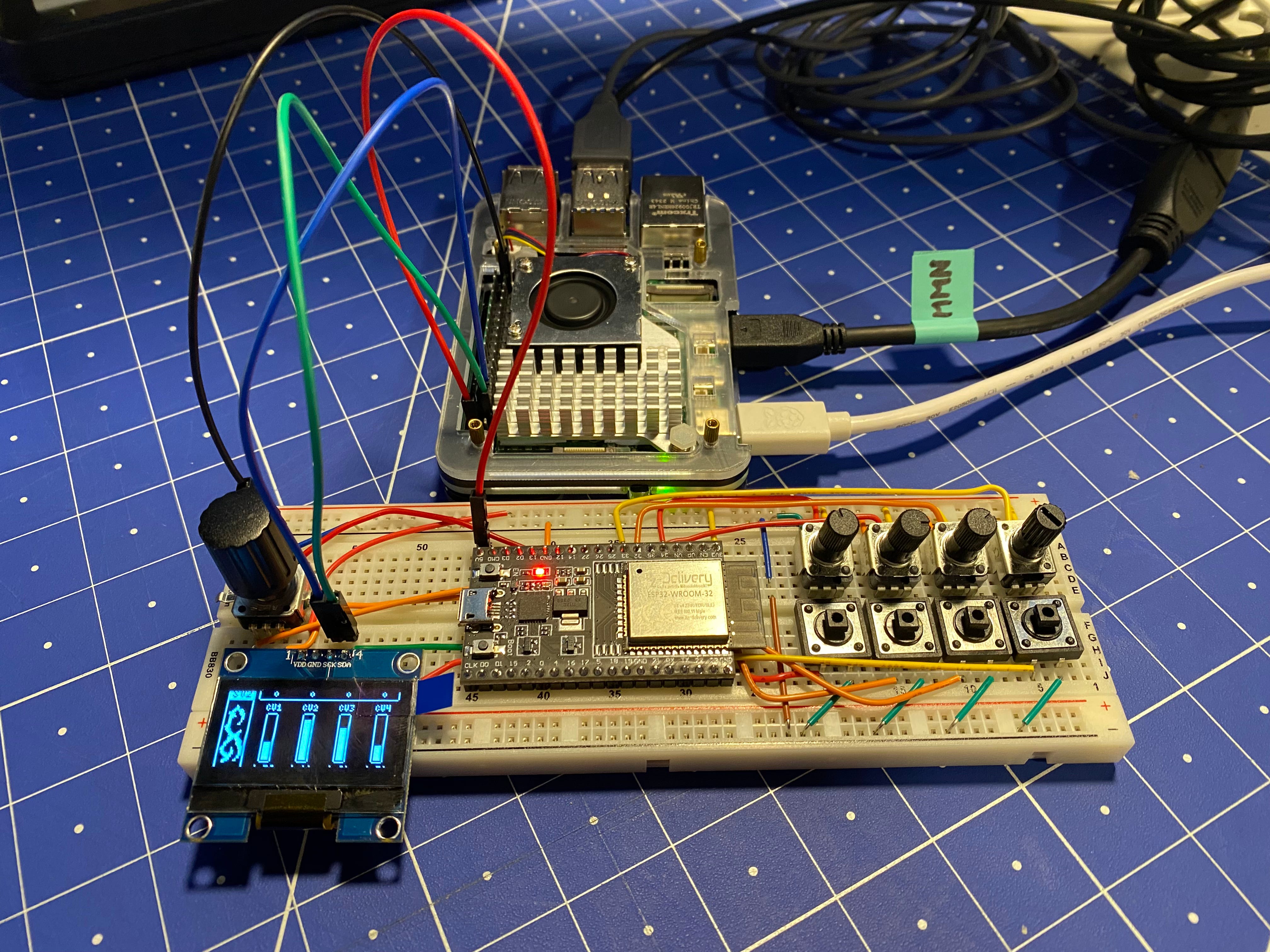
Placing Components and Routing Cables on a Breadboard
I wanted to have a compact prototype on a breadboard, and while the layout was not very complex, keeping an overview of all the connections was a bit of a challenge.
To solve that, I used EasyEDA to create a schematic with all the connections between components. Then, I used the board layout mode to explore part placements and cable routing with a fake breadboard on the silkscreen layer.
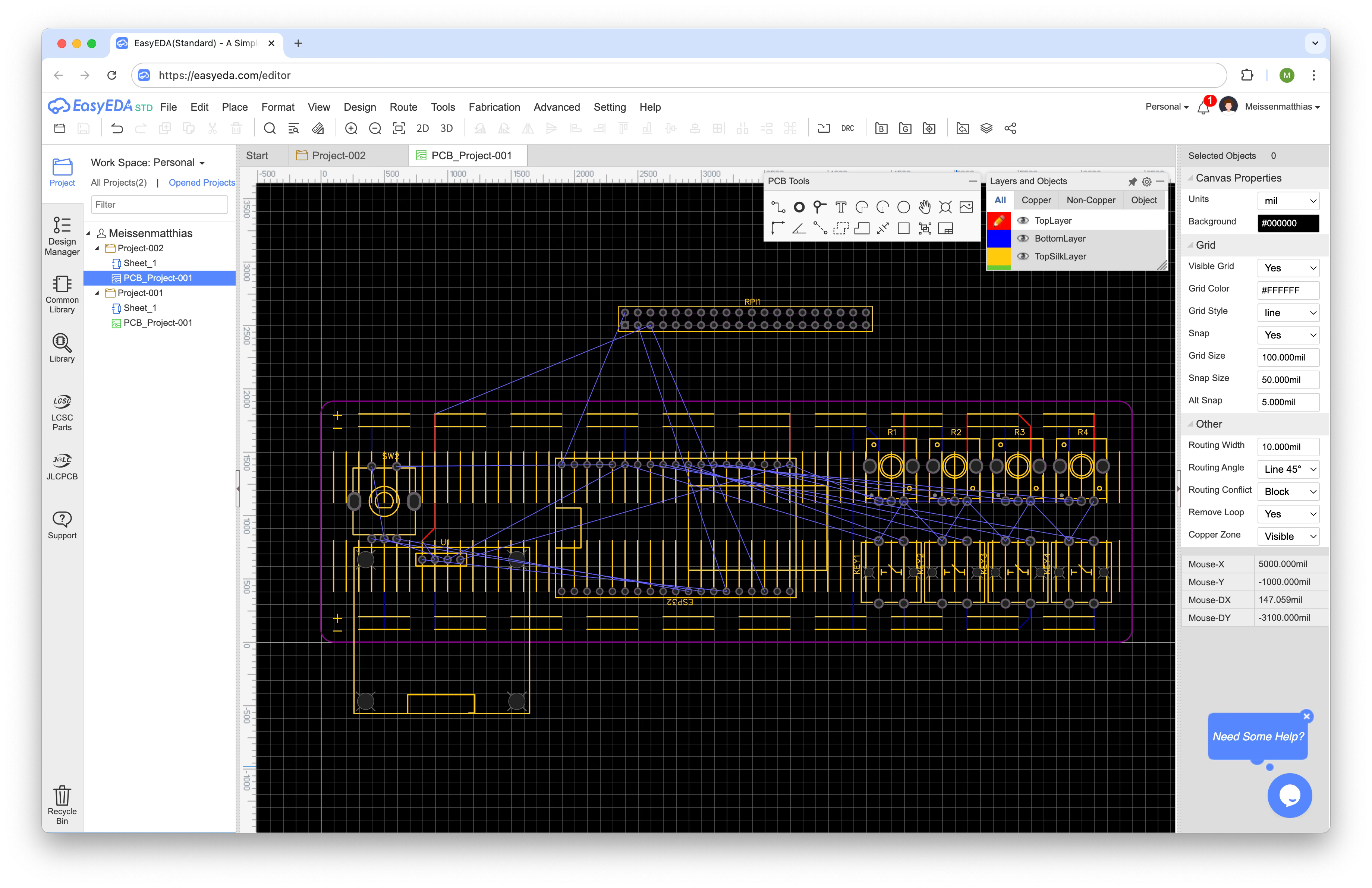
The great thing was to select the same (or somehow similar) components to those I was using and see their footprint directly. In theory, I could take this and refine it to produce a custom PCB with them as well.
Connecting Physical Inputs to Interact with the System
The last step was to modify the existing code to make use of the new input elements. The core was already working through the coordinator pattern. So, turning pots and pushing buttons changed the global state, which adjusted the shader uniforms and was also reflected in the display.
The only new part was the encoder, which I am using to switch between shaders on rotation and toggle screen states on press, though I only have one main screen and a simple debug one for now.
Reflection and Next Steps
Putting this all together was not too easy for me, and there were many details I needed to consider. But I am very happy with how it turned out, and this is a very solid base to continue extending it.
Build an enclosure to make it more robust.
Transfer the circuit to a perfboard and solder the components for a proper connection.
Add some logic for what to show on the display and how to navigate it.
Write new shaders and make full use of all parameters.
Integrate and extend the audio engine.