Building an Audiovisual Synth #4: OLED Screen and Spritesheets
Connecting an OLED screen to the Raspberry Pi over I2C and displaying app state with custom spritesheets.

This part is all about adding a small screen to the Raspberry Pi to display the program state in an interesting way by using spritesheets for custom animation.
Drawing Basic Shapes and Using a Simulator for the embedded-graphics Crate
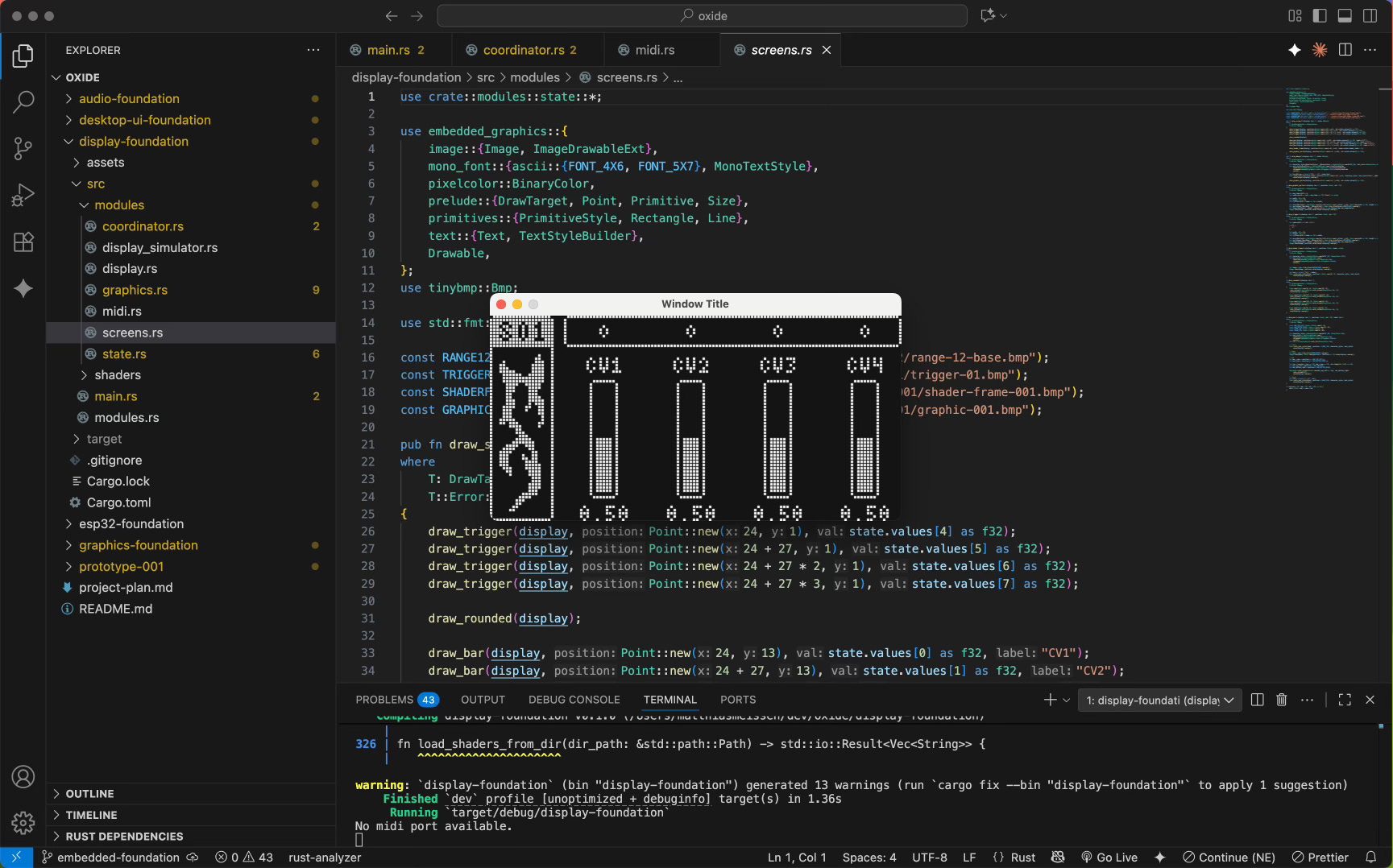
There is a nice library for drawing on small displays called embedded-graphics. It is easy to use and comes with basic elements like lines, rectangles, text, and similar primitives.
A great feature of this library is that it is agnostic about the display it will draw on. This enables you to use the embedded-graphics-simulator as a draw target for easy development without a physical display present.
Using Sprites Made in Aseprite to Draw Custom UI Elements
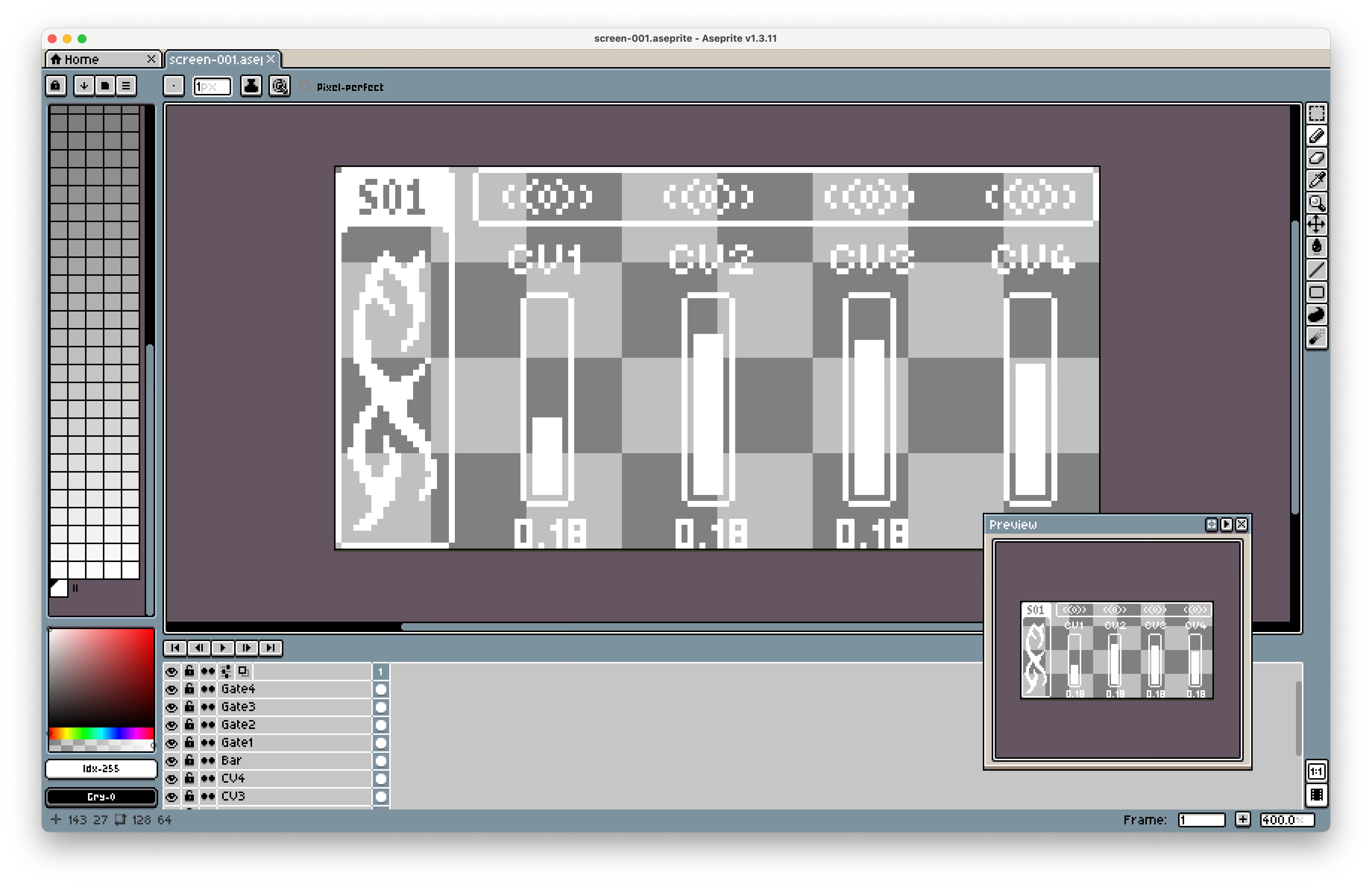
While the basic shapes the library provides are nice, I wanted more flexibility (within my 128x64 pixel constraint).
To achieve this, I drew custom images in a pixel art editor called Aseprite. I exported them as BMP files and used the tinybmp crate to load them into my program.
Animation with Spritesheets and Fixing a BMP Export Issue
Having static custom images is good, but I wanted to create animated shapes (similar to those on Elektron devices). To do this, I drew each frame in Aseprite and exported all of them into a spritesheet, which is a single image containing all the images from a sequence.
However, I encountered a problem with the image data when I tried to load it into my program. The exported files always included an alpha channel, which tinybmp did not support and caused a compile-time error. To fix this, I used ffmpeg to convert the image into the correct format.
Then, within embedded-graphics, there is a method called .sub_image() that lets you display only a specific region of a larger image. This way, you can cycle through the regions and show them step-by-step to create an animation.
Showing System State on the Screen
Now that I had all the elements in place, I was able to connect the display to the application’s state data. This was very simple with the coordinator pattern I already had in place.
I only had to add a new triple-buffer to send state to the display’s draw loop. In there, I created different functions that take parameters and update the screen based on them.
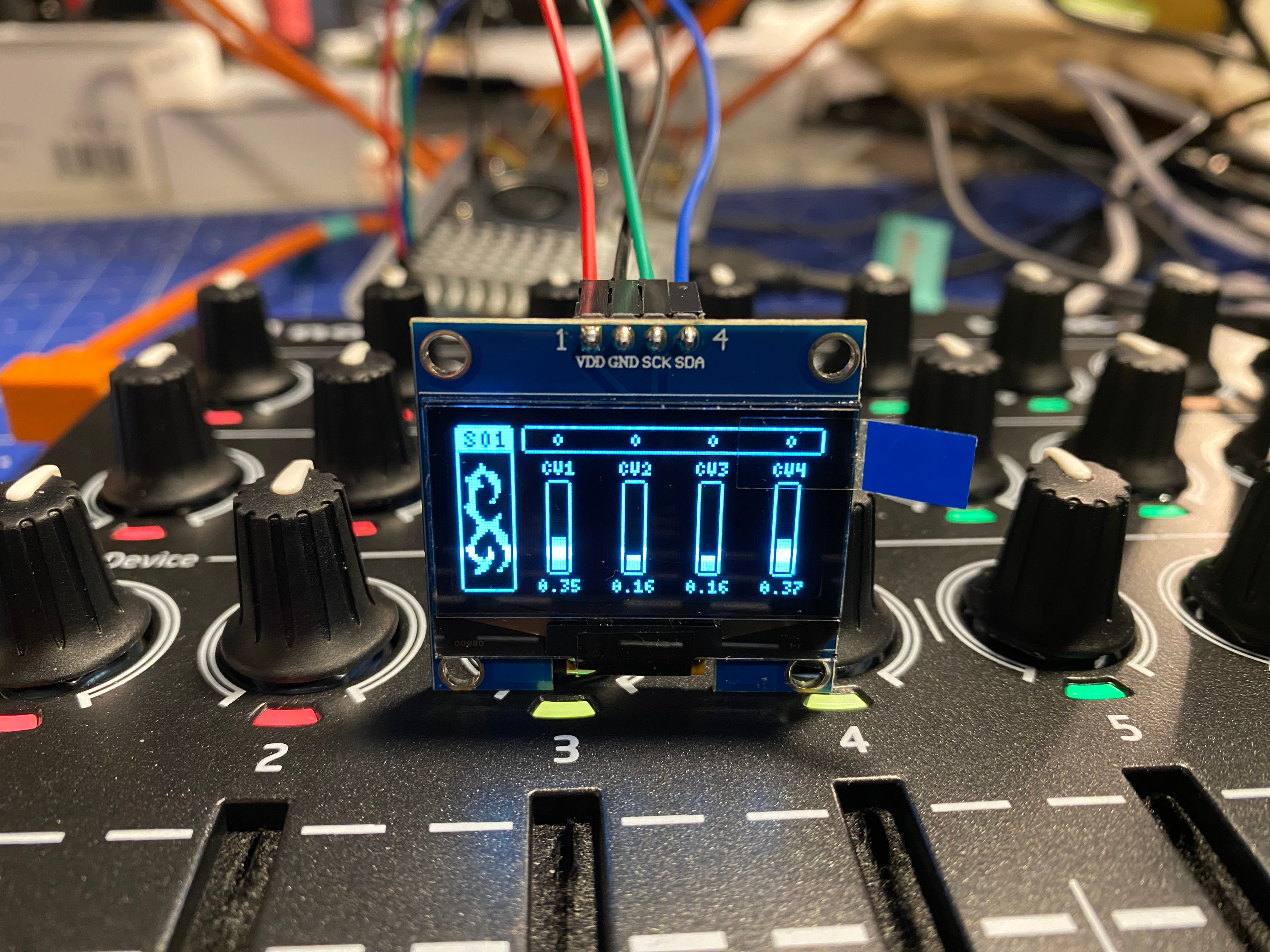
Connecting an OLED Screen to the Raspberry Pi over I2C
After getting all my screens ready in the simulator, it was time to display them on a real screen. Connecting an I2C screen to a Raspberry Pi was way easier than I thought. It requires four pins: VCC (3.3V) and GND for power, as well as SCL (Clock) and SDA (Data) connections.
You then need to add a crate for your specific display and some for using the I2C connection on the Pi. In my case, I used linux-embedded-hal for that.
I initially thought I was using an SSD1309 display, so I installed the crate for it. The connection worked, but the display only showed random pixels when I sent something.
After some research, I discovered that my display was an SH1106 instead. It took me a while to change the code to work with the crate for that display. But in the end, I managed to get it working and learned that reading the documentation is very helpful sometimes.
Conditional Compiling for Specific Operating Systems
When I added the Raspberry Pi-specific crates, the Rust analyzer and compiler started to complain on my Mac since it did not know how to handle them. At first, I had two different projects and was copying things around, but this was quite tedious.
After some research, I discovered that you can specify which dependencies, modules, or lines of code you want to include on compile based on the operating system you are using. This allowed me to have only one project for both my Mac and the Raspberry Pi.
Another thing I learned was to use generics in functions. This helped me to use a generic draw target in the functions that defined how a screen should look. I could then use them on both the simulator and the OLED screen.
So now I have a program that displays a shader on the HDMI output that you can control over MIDI and also shows the app state on the OLED screen. The only thing missing for now is the audio aspect.
Open Topics and Where to Go from Here
Having a screen attached is a great feature and a good basis to build upon. Now I need to figure out what to show on it. Perhaps it is just like progressive enhancement: the whole device should be usable without the screen, but having it makes it more pleasant by making things faster or just by adding some visually pleasing elements.
The next part is all about adding physical controls, like buttons, encoders, or similar components to the device. The idea is to have a dedicated microcontroller (likely an ESP32 or Arduino) that handles reading these inputs and sends the data over I2C to the Raspberry Pi. This might be quite challenging, but let’s see how it goes.